NodeMCU - Introduction
Welcome to the main page of our NodeMCU development, here at Raspberry Valley.
NodeMCU is an excellent hardware, which provides just enough versatility for us to do a majority of our developments. It is Arduino compatible, has a Wifi onboard and has enough kick to power our IoT devices. Whether connecting to gateway or connecting to our cloud solutions.
"NodeMCU is an open source IoT platform. It includes firmware which runs on the ESP8266 Wi-Fi SoC from Espressif Systems, and hardware which is based on the ESP-12 module. The term "NodeMCU" by default refers to the firmware rather than the development kits. The firmware uses the Lua scripting language." [Wikipedia]
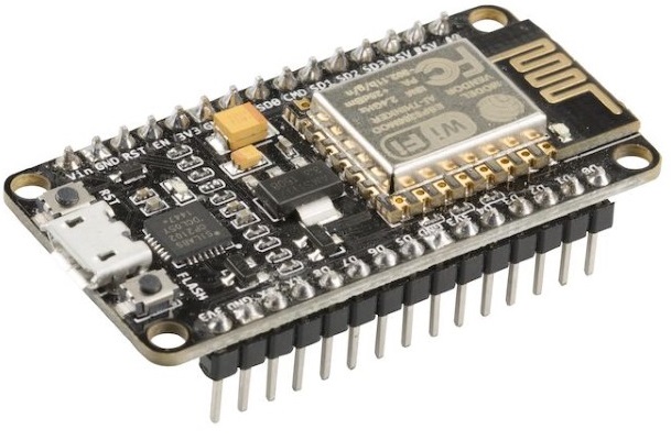
If you like the Arduino, you will love NodeMCU. Without any extra shields, you can achieve common functionality in a small-factor device. You might have noticed that the device ships with the Lua programming language. Don't worry if you're not fluent in this language; you can program the device in C++ (and plug it in into the Arduino software), MicroPython, and many others, including Scratch-like languages. In a majority of cases, we will take the C++ (and Arduino IDE) path.
Pin Layout
Please find below an overview of the pin layout for this board.
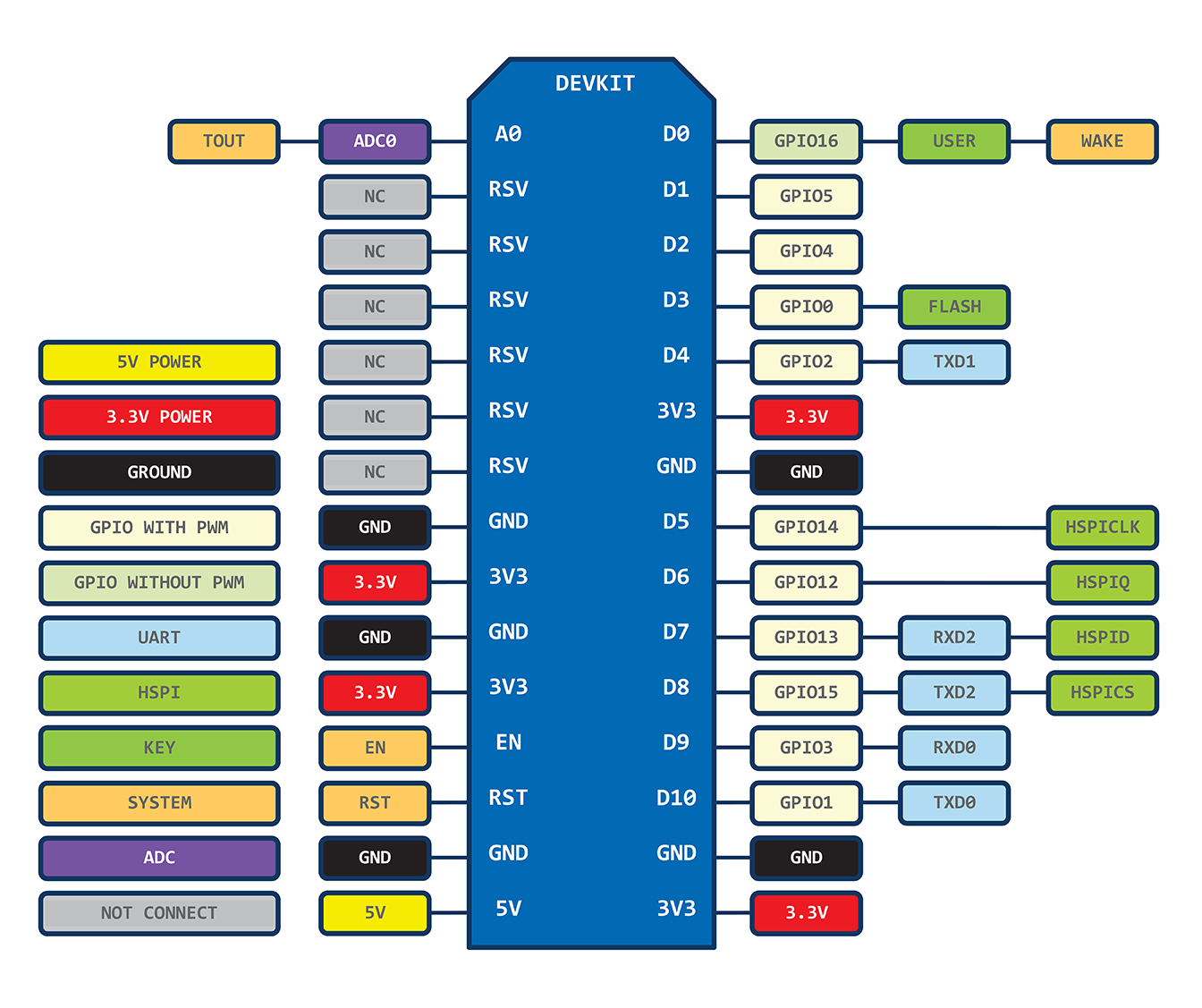
Please note that this causes quite some confusion. The numbers on the pins DO NOT map to the numbers of pins of the ESP8266. For example - pin D1 of the board does not map to GPIO1 as you would expect, but to GPIO5 instead!
The above layout indicates how to interpret the mapping. For clarity, you can also see the mapping list between NodeMCU pins and GPIO below:
- D0 = GPIO16
- D1 = GPIO5
- D2 = GPIO4
- D3 = GPIO0
- D4 = GPIO2
- D5 = GPIO14
- D6 = GPIO12
- D7 = GPIO13
- D8 = GPIO15
- D9 = GPIO3
- D10 = GPIO1
- LED_BUILTIN = GPIO16 (auxiliary constant for the board LED, not a board pin)
Also note, that many libraries include the mapping already, so you don't have to worry about the translation. If you write to D1 for instance, you will get this interpreted correctly as GPIO5 (PIN5). Check the docs.
Setting up in Arduino IDE
Here is a simple walk-through for setting up the device in your Arduino IDE. Basically, you need to add the board to the list of available boards and choose it (together with the appropriate port and speed setup) for NodeMCU development. Using this approach, it is important to note the Lua firmware is overwritten. You can get it back if needed, so no issues.
- We assume you have the Arduino IDE installed. If not, head to Arduino Home, navigate to the 'Software' section, download and install the latest version. You can also install the portable version and can use the setup in another IDE of choice (such Visual Studio Code), but we will not focus on this here
- Open 'Arduino IDE' and click File - Preferences
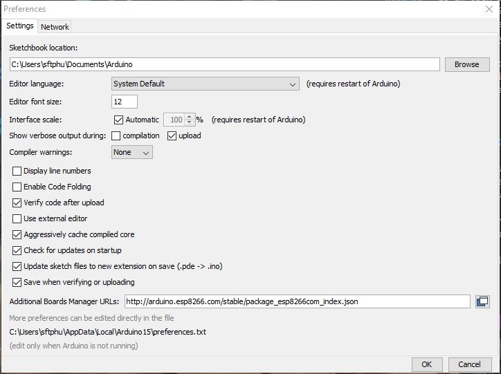
- Copy the URL below into the section Additional boards Manager and click OK to close the Preferences tab
http://arduino.esp8266.com/stable/package_esp8266com_index.json
- Goto Tools - Board ... - Board Manager
- Locate the esp8266 by esp8266 community entry and install the software for Arduino (notice the NodeMCU entry in this board list)
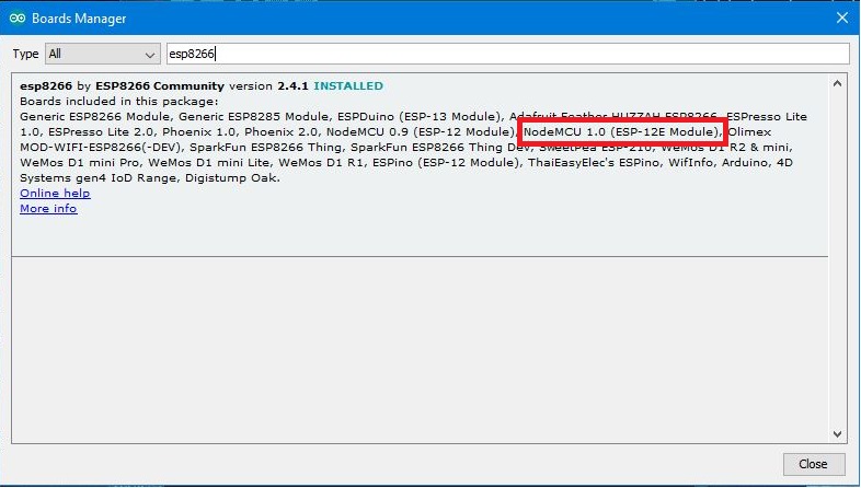
Done. You can now select the NodeMCU in the Boards menu.
NodeMCU WatchDogs
The ESP8266 (and therefore NodeMCU) is a little different than the standard Arduino boards. It has a watchdog(WDT) functionality turned on by default. If the watchdog timer isn't periodically reset then it will automatically reset your NodeMCU. The watchdog is reset every time loop() runs or you call delay() or yield() but if you have blocking code, then the watchdog may time out, resulting in your reset. So a typical code should respect this:
  while(digitalRead(somepin) != LOW) {
    // do action
    yield();
  }
Similarly, the delay() function works to allow background processes to run.
To avoid frustration, please read-up a bit more on the Watchdog features. It will save you some serious headaches. A good overview can be found in this article: ESP8266 Watchdogs in Arduino
Links
- NodeMCU Wikipedia Article
- NodeMCU documentation (Readthedocs.io) - a very nice set of documents related to NodeMCU
- Quick start to NodeMCU on Instructables - A nice guide summarizing setup and blinking an Led (including browser control)
- NodeMCU with Azure and MQTT and Node-RED (Hackster)
- Thingiverse NodeMCU projects
- Comparison of NodeMCU Boards
- ESP8266 Watchdogs in Arduino